Shell-and-tube heat exchangers are cylindrical in shape, consisting of a bundle of parallel tubes surrounded by an outer casing (shell). Both the tube bundle and the shell are designed as pressure containing elements in accordance with the pressure and temperature requirements of the fluids that flow through each of them. The tube-side fluid is isolated from the shell-side fluid either by gasketed joints or by permanent partitions. The Standards of Tubular Exchanger Manufacturers Association (TEMA) define the various types of shell and tube exchangers, as well as design and construction practices.
The shell-and-tube exchanger is by far the most common type of heat exchanger used in production operations. It can be applied to liquid/liquid, liquid/vapor, or vapor/vapor heat transfer services. The TEMA standards define the design requirements for virtually all ranges of temperature and pressure that would be encountered in an oil or gas production facility.
The simplest type of shell-and-tube heat exchanger is shown in Figure 3-1. The essential parts are a shell (1), equipped with two nozzles and having tube sheets (2) at both ends, which also serve as flanges for the attachment of the two channels or heads (3) and their respective channel covers (4). The tubes are expanded into both tube sheets and are equipped with transverse baffles (5) on the shell side for support. The calculation of the effective heat transfer surface is based on the distance between the inside faces of the tube sheets instead of the overall tube length.
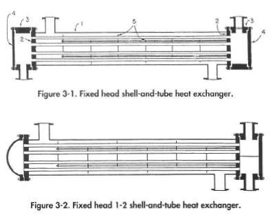
The shell-and-tube exchanger shown in Figure 3-1 is considered to operate in counter-current flow, since the shell fluid flows across the outside of the tubes. Often, in order to maintain a high enough tube velocity to avoid laminar flow and to increase heat transfer, the design is modified so that the tube fluid passes through a fraction of the tubes in two or more successive “passes” from head to head. An example of a two-pass fixed-tube exchanger is shown in Figure 3-2.
An exchanger in which the shell-side fluid flows in one shell pass and the tube fluid in two or more passes is called a 1-2 exchanger. A single channel is employed with a partition to permit the entry and exit of the tube fluid from the same channel. At the opposite end of the exchanger a bonnet is provided to permit the tube fluid to cross from the first to the second pass. As with all fixed-tubesheet exchangers, the outsides of the tubes are inaccessible for inspection or mechanical cleaning. The insides of the tubes can be cleaned in place by removing only the channel cover and using a rotary cleaner or wire brush.