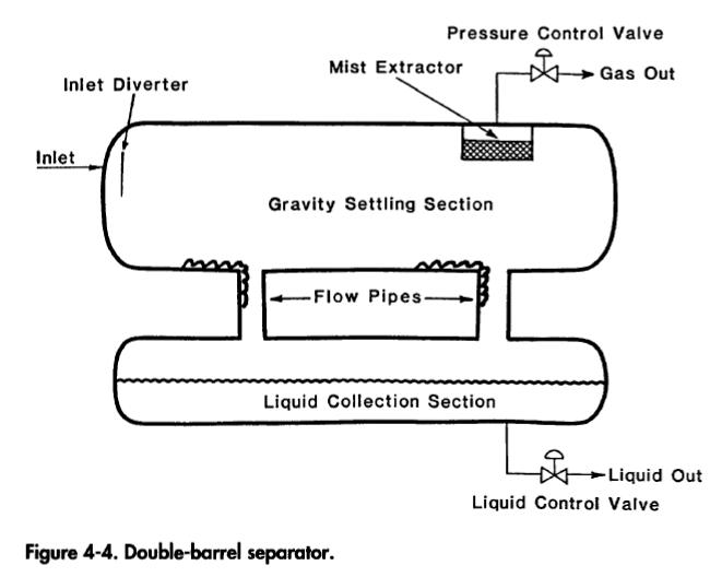
Cyclone separators are designed to operate by centrifugal force. These designs are best suited for fairly clean gas streams. The swirling action of the gas stream as it enters the scrubber separates the droplets and dust from the gas stream by centrifugal force. Although such designs can result in significantly smaller sizes, they are not commonly used in production operations because (1) their design is rather sensitive to flow rate and (2) they require greater pressure drop than the standard configurations previously described. Since separation efficiency decreases as velocity decreases, cyclone separators are not suitable for widely varying flow rates. These units are commonly used to recover glycol carryover downstream of a dehydration tower. In recent years, demand for using cyclone separators on floating facilities has increased because space and weight considerations are overriding on such facilities.Two-barrel separators are common where there is a very low liquid flow rate. In these designs the gas and liquid chambers are separated as shown in Figure 4-4. The flow stream enters the vessel in the upper barrel and strikes the inlet diverter. The free liquids fall to the lower barrel through a flow pipe. The gas flows through the gravity settling section and encounters a mist extractor en route to the gas outlet. The liquids drain through a flow pipe into the lower barrel. Small amounts of gas entrained in the liquid are liberated in the liquid collection barrel and flow up through the flow pipes. In this manner the liquid accumulation is separated from the gas stream so that there is no chance of high gas velocities re-entraining liquid as it flows over the interface. Because of their additional cost, and the absence of problems with single vessel separators, they are not widely used in oil field systems.
Another type of separator that is frequently used in some highgas/low-liquid flow applications is a filter separator. These can be either horizontal or vertical in configuration. Figure 4-5 shows a horizontal two-barrel design. Filter tubes in the initial separation section cause coalescence of any liquid mist into larger droplets as the gas passes through the tubes. A secondary section of vanes or other mist extractor elements removes these coalesced droplets. This vessel can remove 100% of all particles larger than about 2 microns and 99% of those down to about 1/2 micron. Filter separators are commonly used on compressor inlets infield compressor stations, final scrubbers upstream of glycol contact towers, and instrument/fuel gas applications. The design of filter separators is proprietary and dependent upon the type of filter element employed.

In applications where there is very little liquid flow, often a horizontal separator will be designed with a liquid sump on the outlet end to provide the required liquid retention time. This results in an overall smaller diameter for the vessel.